( 40+ simple 555 timer circuits & projects simple adjustable timer circuit with 555 ic adjustable on off timer (using 555 astable mode) The above switching arrangement will allow two motors to be controlled from a single pushbutton station.
Simple Delay Timer Circuits Explained
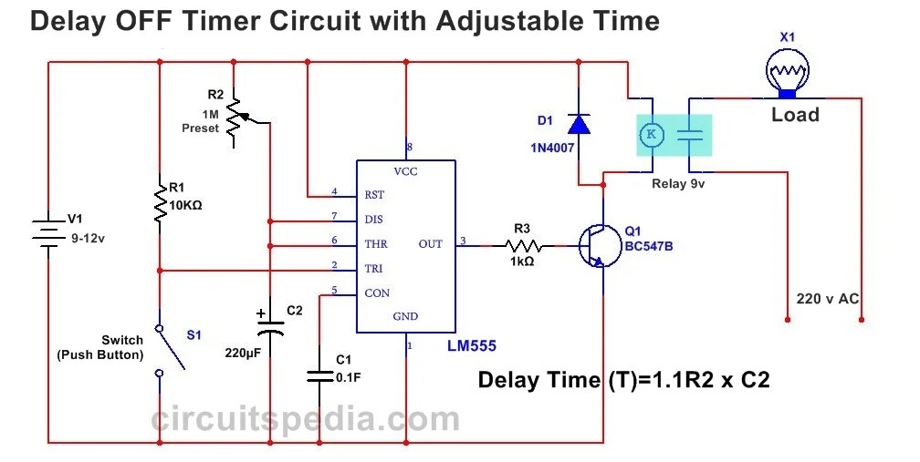
Off Delay Timer Circuit Diagram. Web eight different timing vis are designed and tested. Web 555 timer delay off circuit diagram the above circuit uses a 555 timer u1 in mono stable mode. Time delay relay circuit diagram.
Web Switch On Delay Timer Circuit Diagram Power On Delay Timer If You Want To Switch On Any Load After Some Moment Or Some Duration Then You Can Use This Timer Circuit.
Web you can also adjust the off delay time up to 20 minutes with a 1m pot. All are functionally same but the delaying operation will be varied. The easiest way is to turn on the light only when needed and turn it off when not.
Web The First Circuit Diagram Shows How A Transistors And A Few Other Passive Components May Be Connected For Acquiring The Intended Delay Timing Outputs.
The relay is not energized when there is a logical zero at the base of t1. A delay timer off is such a circuit through which your connected device automatically gets off after some time of turning on it. The off delay timing diagram can be interpreted in the same manner as the on delay timing diagram.
On Energization Of The Timer Coil, The Timer Activates And Changes Its Contact State From No To Close Or Nc To Open.
Web off delay timer timing diagram. ( 40+ simple 555 timer circuits & projects simple adjustable timer circuit with 555 ic adjustable on off timer (using 555 astable mode) Web what is the delay timer off circuit?
Web Here A Circuit Diagram Of Delay Power Off Timer Circuit For Off Time Delay, Switch Off Delay Timer Circuit Diagram.
That means that there is an rcpair (p1 + r3 and c1) for the ‘off’ time and another pair (p2 +r4 and c2) for the ‘on’ time. Web #1 running into wall on these things but found one willing to make. The important factor to remember when interpreting the off delay timing diagram is to remember that an off delay timer contains instantaneous contacts.
Web However, These Methods Are Cost Ineffective.three Circuits Are Explained Here Are 1)Simple Adjustable Timer Using 555 Ic,2)A Cyclic On/Off Timer Using 555 Ic,3)Adjustable Timer Using Arduino.
If you want to use this circuit on ac then just simply add a 5vdc relay. June 23, 2023 by apichet garaipoom. It also has a potentiometer to adjust the time delay, where you can increase of decrease the time delay by just rotating the potentiometer.
This Circuit Is Very Useful In The Protection Of Any Load.
Switch on delay timer circuit read more » If once push button is pressed, it drives pin2 of timer momentarily to ground that triggers the 555 to deliver a high output at pin 3 to drive a relay through q1 being fed with 2.2k resistor. The transistor has been provided with the usual base resistor for the current limiting functions.
Today We'll Discuss How You'll Make An Easy Delay Timer Circuit.
Web using timers we can delay the circuit operation. Web in this project we are going to design a simple time delay circuit using 555 timer ic. This is a protection circuit to protect any electrical or electronic equipment and appliance from sudden high or unstable voltage.
Each Diagram Shows How To Connect The Timer’s Terminal Blocks, As Well As How To Wire The Outlets And Components.
Web last updated on: Time delay relay circuit diagram. Three types of timers are the most commonly used in the electric circuit.
It’s Important To Note That There Are Two Main Wiring Diagrams For These Types Of Timers—One For Ac And One For Dc.
Timer circuit for delay switch off. As a result, the current output is much higher than a regular npn transistor. Web looking at the circuit diagram below we can see that two inexpensive ic 4060 have been wired up as two independent timer modes.
The Timer Module Is Usually Either Mechanical Or Digital, And Its Purpose Is To Measure And Store A Programmed Period Of Time.
And after a while, the load will off. Web the most basic components of a typical off delay timer circuit diagram are a timer module, power supply, and output relay. But in practice, we often forget to turn off the lights even when they are not needed.
The Way The Circuit Works Is That Once You Press The Push_Button From Then The Load Which Is Connected With The Circuit Will Work.
A led which is used here just indication purposes behaves like the collector load of the. Normally closed time closed off delay contact (nctc) Web eight different timing vis are designed and tested.
However Though The Timing Settings Are Independent For The Two Sections, These Are Coupled With Other Such That Their Initialization Become Very Much Interconnected.
In this article, i have shared the required components, complete circuit diagram, pcb layout, and all other details for this simple 555 timer project. This circuit consists of 2 switches one for start the delay time and other for reset. Web things you need to know about off delay timer circuit?
Automatic Switch Off After Delay Duration Time Using 555 Timer.
Because we should always save battery power. Web when it comes time to wire up a dayton off delay timer, the wiring diagram is key. The above switching arrangement will allow two motors to be controlled from a single pushbutton station.
Web Circuit 1 Power On Delay Timer Circuit The Delay Timer Is A Device That Is Used To Take Some Duration Be]Fore Switch On The Main Input Supply To Any Equipment.
What value ohms variability to get the delay off from 1 to 20 seconds? The power supply is the source of energy for the circuit. This is a simple transistor circuit with some other complementary components.
When Appliance Or Load Is Turn On Then After A Fix Time Duration Automatic Switch Off.
Web 555 timer delay off circuit diagram the above circuit uses a 555 timer u1 in mono stable mode. These timed contacts are in series with motor starter m2. Timing can be adjusted by adjustment of preset.

Adjustable Auto On Off Delay Timer Circuit Using 555 IC
555 Delay OFF Timer Circuit For Delay Before Turn OFF Circuit

On Off Delay Timer Circuit Diagram Simple Delay Timer Circuits

Simple Delay Timer Circuits Explained

Simple Delay Timer Circuits Explained

IC 555 Delay Timer circuit on off delay circuit Electroinvention

Simple Delay Timer Circuits Explained

Relay OFF Time delay timer by using NPN Transistor and Capacitor
